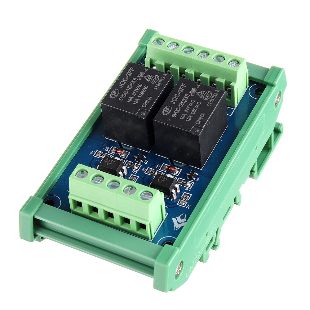
5pcs 2CH Channel Optocoupler Isolation Relay Module 5V SCM PLC Signal Amplifier Board

5pcs 2CH Channel Optocoupler Isolation Relay Module 5V SCM PLC Signal Amplifier Board
5pcs 2CH Channel Optocoupler Isolation Relay Module 5V SCM PLC Signal Amplifier Board5pcs 2CH Channel Optocoupler Isolation Relay Module 5V SCM PLC Signal Amplifier Board5pcs 2CH Channel Optocoupler Isolation Relay Module 5V SCM PLC Signal Amplifier Board


Structural Features:


1. Use Hongfa relay, stable and reliable performance;

2. Compatible with two input modes of positive control and negative control;

3. Each channel has an LED action indicator for a more intuitive understanding of product performance;

4. Each channel adopts optocoupler isolation to enhance anti-interference performance and isolation performance;

5. At the same time, the power supply and the "IN" control terminal are independently controlled;

6. The module adopts the standard "DIN" rail-type installation design, which is convenient and quick to install, firm and stable.


Technical Parameters:


1. Trigger signal: DC5V

2. Each trigger signal current: 5mA

3. Power supply voltage: DC5V

4. Each coil current: 18.8mA

5. Contact type: one normally open and one normally closed (single pole)

6. Maximum load current of each contact: 10A

7. Action time: below 12ms

8. Reset time: less than 4ms

9. Maximum switching frequency: 18000 times / hour

10. Mechanical life: more than 20 million times

11. Relay installation: plug-in type (No)

12: Module installation method: DIN standard rail installation

Positive control wiring introduction:


1. Power input terminal:

VCC is connected to the positive voltage, GND is connected to the negative voltage, and S / S is connected to the negative voltage

IN1, IN2 are connected to positive voltage control, IN1 controls  terminal, IN2 controls K2 terminal

2. Control device output:

The output terminal is clearly marked with 234, 3 is a common point, 2 is normally open, and 4 is normally closed. K1, K2 means two relays work.


Negative control wiring introduction:


1. Power input terminal:

VCC is connected to the positive voltage, GND is connected to the negative voltage, and S / S is connected to the positive voltage

IN1, IN2 are connected to negative voltage control, IN1 controls  terminal, IN2 controls K2 terminal

2. Control device output:

The output terminal is clearly marked with 234, 3 is a common point, 2 is normally open, and 4 is normally closed. , K2 means two relays work.

Package includes:

5 x Relay board


5pcs 2CH Channel Optocoupler Isolation Relay Module 5V SCM PLC Signal Amplifier BoardSee detail


Popular posts from this blog

MQ137 Gas Sensor Module MQ-137 Ammonia Sensor Module NH3 Sensor Module

Buy MQ137 Gas Sensor Module MQ-137 Ammonia Sensor Module NH3 Sensor Module Description:   Size: 32mm X22mm X30mm length * width * height Main chip: LM393, NH3 gas sensing probe Working voltage: DC 5V   Features:   1. It has a signal output indicator indication; 2, dual signal output (analog output and TTL level output); 3. The TTL output valid signal is low level; (when the output low level, the signal light is on, it can be connected to the IO port of the single chip) 4. The analog output increases with increasing concentration, and the higher the concentration, the higher the voltage; 5. High sensitivity and selectivity to ammonia; 6. Has a long service life and reliable stability; 7. Fast res ponse recovery features; 8. With mounting holes for easy installation; 9. The probe can be plugged and unplugged for easy testing.   Application:   Harmful gas detection device for home and environment, suitable for the detection of ammonia vapor, ammonia gas sensor test concentration rang...

[lzcgs] Wireless bluetooth Speaker Double Units 3D Sound LED Display Alarm Clock FM Radio Soundbar Desktop Speaker AUX TF Card for Phone Laptop COD

Buy Wireless bluetooth Speaker Double Units 3D Sound LED Display Alarm Clock FM Radio Soundbar Desktop Speaker AUX TF Card for Phone Laptop COD Specifications: Peak power: 6W Charging input: 5V Frequency response: 100Hz-20KHz Signal-to-noise ratio: 85dB Distortion: ≤0.5% Impedance: 4 Ω Inetrface: 3.5mm Color: Black bluetooth version: 5.0 Material: ABS Size: 385*45*60mm Package Included: 1 * bluetooth Digital Alarm Clock Speaker 1 * Charging Cable  1 * Manual  Wireless bluetooth Speaker Double Units 3D Sound LED Display Alarm Clock FM Radio Soundbar Desktop Speaker AUX TF Card for Phone Laptop COD Buy Now

ESP8266 ESP-12S A9G GSM GPRS+GPS IOT Node Development Board Module with All in One WiFi Cellular GPS Tracking Module

Buy ESP8266 ESP-12S A9G GSM GPRS+GPS IOT Node Development Board Module with All in One WiFi Cellular GPS Tracking Module Overview:   1. ESP-12S A9G GSM GPRS+GPS IOT Node, an all-in-one cellular phone module with WiFi module with that lets you add location-tracking, text, SMS and data to your project. This IOT node has both WiFi and GPRS support. That means it's perfect for just about any wireless or Internet-connected project. 2. This is the ESP-12S A9G GSM GPRS+GPS IOT Node, which based on the ESP-12S and the cellular phone module A9G. TWO modules all are come from Ai-thinker. With built in USB and battery charging, it is a really IOT development board. It is very useful on your IOT project. 3. At the IOT Node’s heart is an ESP8266 WiFi microcontroller clocked at 80 MHz and at 3.3V logic. This microcontroller contains a Tensilica chip core as well as a full WiFi stack. You can program the microcontroller using the Arduino IDE for an easy-to-run Internet of Things core. We wired u...